Cantilever Rack Installation Guide
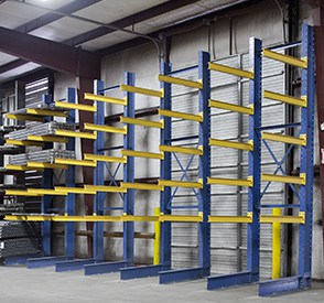 Request our installation guide for assembly, installation and use of Cantilever Storage systems. Use to familiarize all users with every aspects of installation and use of Cantilever Racks.
Site preparation
The slab on which the cantilever column and bases are placed must be able to support the fully loaded weight of the cantilever storage system. Minimum concrete underlayment must be 3,000 PSI. Seasonal ground conditions, e.g. rain, permafrost thaw, potential subsidence must be taken into account. A ground survey may be required for proper installation. Tall storage systems may be subject to height restrictions and wind constraints and local permit requirements. The installation site must be level for the storage system to be stable. Appropriate preparation may need to be taken to prepare concrete slabs and or exterior areas. Non concrete areas are not approved for cantilever installation.
**IMPORTANT**
Cantilever Storage systems must be level and adjoining cantilever columns must be at the same height. If shimming is required to adjust the level, shims should be of steel plates as broad or broader than the base structure width. Cantilever bases AND columns should be shimmed as needed to assure proper level alignment.
Assembly
Bracing
Bracing must be installed between each pair of Cantilever columns. Twelve foot columns require one X-Brace between columns. Sixteen foot columns require one X-Brace and one Strut Brace between columns. Columns must be installed in sections of 2 or more columns for stability. Bracing should be placed between each column regardless of the length of the row segment or the total number of columns per row — no spaces should exist.
Anchoring
Upright columns and bases must be anchored to the floor using ¾” diameter wedge anchors into a concrete slab (Columns require 2 anchors per column, bases require 4 anchors per base). Anchors should be embedded to a minimum depth of 3 ¾” into a concrete slab.
Fasteners
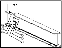
Bases should be attached to Cantilever Columns with (6) ea. ¾” Bolts/Nuts
Arms should be attached to Cantilever Columns with (4) ea. ¾” Bolts/Nuts
X-bracing should be attached to Cantilever Columns with (2) ea. ¾” Bolt/Nut/Washer
All component fasteners must be tightened to the following torque settings:
¾” Grade 8 bolt/nut – 250 Foot Pounds
¾” Grade 8 bolt/nut – 85 Foot Pounds
¾” Wedge Anchor – 150 Foot Pounds
Safe Use of Cantilever Racks
It is essential to system stability that columns and arms are not overloaded or damaged during use. Additionally, all personnel using Cantilever Storage Systems should be aware of the potential hazards involved
– When loading equipment on cantilever arms care needs to be taken that the arms don’t get damaged
– Ensure Cantilever Storage Systems are installed on firm even concrete.
– If needed, use metal shims to adjust the bases and column to ensure it is stable, and the arms are even
– Do not allow the arms to tip forward.
– Do not load on the tip of arms
– Ensure assistance is given to direct the forklift / crane operator to place the load carefully and evenly across all arms in the system
– Ensure all personnel in the proximity of the storage system are positioned so that in the event of the loading or unloading mishap they cannot get hit by the falling load
– Keep hands and body parts away from the storage system while loading – unloading
– Do not crawl under loaded storage system
– Do not climb on the storage system
– Don’t drop loads onto the arms.
– Ensure heaviest equipment is stored on lowest levels
– On tandem racks, keep loads evenly spread on each side
CONSIDERATIONS FOR CANTILEVER RACKS
Determine the number and spacing of arms
The load must be supported the appropriate number of arms to prevent load deflection. (fig. 1. – A.2)
– deflection may cause damage to the load being stored as well as the arms (fig. 1.- A.1)
– place the load over two wooden blocks (to represent cantilever arms) as shown in next slide
– If deflection is not present it is acceptable to use a two arm system as long as the arms can support the load
– If the load shows deflection use three blocks as shown in Fig 1. – A.3 or four blocks as in fig. 1. – A.4.
IMPORTANT:
The load should overhang the end arms by one-half the distance from the end column centerline to next column centerline with 12” between each load.
Failure to observe this measure may cause an overload condition on the arms.
Determining the Load Capacity Requirements of the Cantilever System
Calculating Capacity requirements for Cantilever Columns (See Chart)
| Cantilever Rack | Specs | Wgt | Capacity (lbs) |
|---|---|---|---|
| 12′ Column (144″) | 5″ x 10″ Structural | 210.9 | 12,000/side |
| 16′ Column (192″) | 5″ x 10″ Structural | 276.7 | 10,000/side |
| 20′ Column (240″) | 5″ x 10″ Structural | 334.3 | 10,000/side |
| 36″ x 4″ Arm | I-Beam | 24.7 | 2400 |
| 48″ x 4″ Arm | I-Beam | 31.5 | 1840 |
| 48″ x 4.75″ Arm | I-Beam | 39.5 | 2500 |
| 54″ x 5″ Arm | I-Beam | 45.5 | 2344 |
| 54″ x 5.5″ Arm | I-Beam | 45.5 | 3425 |
| 60″ x 6.25″ Arm | I-Beam | 68.6 | 3500 |
The load capacity yield of the Cantilever Column is :
A 12’ Cantilever Column can support up to 12,000# per side per column
A 16’ Cantilever Column can support up to 10,000# per side per column.
A 20′ Cantilever Column can support up to 10,000# per side per column.
In calculating the total capacity users must consider the deflection of the load and the total weight required per level.
Upon determining the load weight requirement per level, this number can be divided into the total capacity of two columns to determine how many levels and or columns will be needed for the total system requirement.
IMPORTANT:
The total weight of the storage system and its load needs to be considered when determining installation location to ensure the area will be able to bear the load without collapsing. The load placed on the base does not diminish the rated capacity of the column. Therefore, the heaviest loads should be placed on the base.
Proper Loading and Capacity of Cantilever Arms
The load should never exceed the length of the arm.
– A 48″ wide bundle of plywood requires a 48″ long arm
-Bundles of steel 24″ wide require a 24″ or longer arm and so on.
– Allow 1-2” extra to ensure that the load does not overhang the Cantilever arm.
Determine the Load & Capacity Requirements of the Cantilever Rack System
Determine the weight per level and divide the weight by the not to exceed capacity of one arm to calculate how many arms will be needed to support the evenly distributed load in the system.
Load for individual 48” x 4” Cantilever arms may not exceed 1,900#.
Load on 12’ tall Cantilever Columns may not exceed 14,300# per side (per column).
Load on 16’ tall Cantilever Columns may not exceed 14,300# per side (per column).
To determine the total number of Cantilever Columns / Arms needed in a Cantilever Storage system, you must take into account the length of the load, total weight on each level and total weight on the system.
Examples:
A. User needs to put 5,000# per level on 2 levels (10,000# total). This requires a basic system of 2 columns with 4 arms.
B. User needs to put 10,000# per level on 2 levels (20,000# total). This would require a system of 4 columns with 8 arms.
In a storage system if a user can place some of that load weight on the base instead of a cantilever arm, you may be able to reduce the number of columns required.
Correct loading of racks
Rated arm capacities may be seriously diminished if proper loading techniques are not observed.
– Loads should be placed to provide an even loading on each arm
– Loads create a greater bending moment on the arm the further it is placed from the column.
– Exceeding the loading capacity can permanently distort the arms, overstress column material and or welding on the material and lead to a catastrophic failure

IMPORTANT:
The load placed on the base does not diminish the rated capacity of the column. Thus, the heaviest loads should be placed on the base.